by Bruce Tharpe

One of the great things about this design is the huge amount of room available to install all of your radio, fuel, retract, and turbine components. In an effort to keep these instructions up to date, you will see photos of several different Reactions including the original ARF (short nose) and the X version (long nose). Click on any of the photos for a larger image. If you have any questions that are not covered here, please contact me or PST directly and we will do our best to help.


QUICK INDEX TO ASSEMBLY MANUAL TOPICS

Hardware Package
Hooking Up the Ailerons
Hooking Up the Flaps
Prep the Wing for Wiring and Air Lines
Fin and Rudder
Hooking Up the Elevator
Elevator Pushrod Assembly
Turbine Installation
Turbine Heat Shield Installation
2.5-Liter Main Fuel Tank Installation
3.8-Liter Main Fuel Tank Installation
Optional One-Liter Fuel Cell
Optional One-Liter Smoke Tank
Header Tank Installation
Retracts and Brakes Installation
Wing Fairings
Fuselage Assembly
Canopy/Hatch Assembly
Various Equipment Installations - Final Touches
Mounting the Tail Surfaces
Optional Speed Brake
Balance Range and Control Throws


HARDWARE PACKAGE (Click on image below for larger picture)


HOOKING UP THE AILERONS

Click to Enlarge Click to Enlarge Click to Enlarge


GENERAL INSTRUCTIONS
- Always sand and clean surfaces (wipe with alcohol or acetone) before gluing.
- Use a high-quality epoxy such as Hysol 9462, BVM Aeropoxy, or 30-minute epoxy mixed with milled fibers for all gluing tasks.
- As you can see in the photos, I leave a healthy fillet of epoxy at the base of my control horns. To my way of thinking, the extra strength outweighs the poor appearance. Besides, most of the horns are on the bottom and normally out of sight. - Supplied mounts are sized for JR servos. Other servos may require the mounts to be trimmed for best fit. - Some of my mounts were not glued square and true at the factory. Sand the mounts and/or add spacers if necessary to make sure the mount is not twisted when glued to the hatch.
- Test a clevis in the control horns to make sure the pin fits snug, but not tight. I needed to go through mine with a 1/16" drill bit to open them up slightly.
- In general, it is better for flutter resistance to hook your linkage to the outermost hole in the control horn, and the innermost hole in the servo arm, as shown in the final photo.
- Be certain that the linkage does not bind or "catch" in the slot.


HOOKING UP THE FLAPS

Click to Enlarge Click to Enlarge Click to Enlarge


GENERAL INSTRUCTIONS
- Flap control horns and servos are installed just like the ailerons.
- One servo will need to be reversed. Hitec servos (as shown) can be individually programmed. Futaba offers a Y-connector with an adjustable reverser (SR-10). A servo matching device like the Matchbox will also work. If you have enough receiver channels, you can plug the flap servos into separate channels and program them in the transmitter.
- It is important to be precise with your setup. The flaps must deflect equally, at least 60 degrees.

- IMPORTANT UPDATE! Add two screws to each hatch, through the fiberglass and into the wood servo mounts for extra security (see photo above, right). This goes for all hatches - ailerons, flaps, and rudder. Use the same screws that are used for mounting the hatches.


PREP THE WING FOR WIRING AND AIR LINES

Click to Enlarge PST provides a couple of access holes in the wing panels, but I did not like their positions. The existing hole on the top surface of the wing is too far aft, conflicting with a fuselage bulkhead when assembled. I cut a new hole in the top, about 1" diameter and installed a rubber grommet (not provided) to protect the wiring and air lines. The servo lead from the flap servo should reach to this hole. I use a 12" extension on the aileron servo lead.

In the wing root, I thought the larger hole closer to the trailing edge was easier for routing air lines away from the wheel well, but you do have to trim away the fiberglass. There is no clearance for a grommet, so sand the edges smooth and that should be adequate to protect the air lines.


FIN AND RUDDER

Click to Enlarge Click to Enlarge Click to Enlarge
Click to Enlarge Click to Enlarge


GENERAL INSTRUCTIONS
- Clean the three point hinges with alcohol, then lubricate the center joints. Some like to use a drop of oil, but I prefer a dab of petroleum jelly. Use a heat gun to "melt" the dab into the joint, and flex it a few times. When cool, the petroleum jelly will be less likely to run than oil.
- Use epoxy to glue in the hinges. For this model, it is best to position the hinge joint as deep in the rudder as you can. Glue the hinges into the rudder first, making sure they swing freely. You can allow the epoxy to dry, then glue the hinges into the fin with a fresh batch of epoxy if you wish. However, I prefer to do the job one step, because you can then deflect the rudder a few times before the epoxy dries which will automatically self-align the hinge points.
- When installing the hatch/servo mount assembly, I noticed the plywood mount made contact with the opposite side of the fin. A few swipes with the sanding block as shown in the photo provided clearance.
- The last photo shows a receiver, switch, and battery that I used during setup.


HOOKING UP THE ELEVATOR

Click to Enlarge Click to Enlarge Click to Enlarge


GENERAL INSTRUCTIONS
- Use the one long control horn for the elevator. Mine had a shallow cut mark near the base, which I ignored. The horn should fit deep into the elevator slot. I drilled a couple of glue holes in mine for extra security. Remember to roughen the surface with sandpaper.
- There is some flexibility in the actual position of the horn. The final position is not critical. I tried to glue it in as deep as possible, then checked the clearance with the fuselage before it dried.
- Notice the elevator servo is mounted with the servo arm closest to the elevator.
- I had to file the metal elevator mount slightly to fit my Hitec servo.
- No mounting screws are provided for the elevator servo. I used 3-48 x 3/4" screws with lock nuts. - The servo arm must be positioned properly and the servo arm screw must be tightened securely before the mount is bolted into the fuselage.
- The elevator servo access hatch is mounted just like all the other hatches, with a flat-head screw in each corner.


ELEVATOR PUSHROD ASSEMBLY

NOTE: The total length shown above should work for nearly any servo installation. However, it would be smart to confirm this by measuring from the elevator servo arm to the holes in the elevator control horn. Adjust the length of your threaded rods if necessary to fit properly.

1. Bend the end of one threaded rod 90 degrees, 3-9/16" (9 cm) from the threaded end.
2. Insert the bent end into one of the holes in the carbon fiber tube.
3. Trial fit a grooved dowel. Enlarge the groove if necessary for a snug fit.
4. Repeat for the opposite end of the pushrod assembly.
5. Remove the dowels and rods, then re-install them using plenty of high-strength epoxy.
6. When dry, wrap each end with the supplied carbon strips. Coat the strips with CA or epoxy.


TURBINE INSTALLATION

This section shows the installation of the PST J800R, the recommended turbine for the Reaction ARF. Other turbines can be installed, but may require cutting the plywood turbine mounting rails to the proper width. The rails show the cut lines for the PST J1300R. If using some other turbine, dry fit the rails and measure carefully to determine how much needs to be trimmed off each rail to fit your turbine.

Click to Enlarge Align the Turbine with the Fuselage. The correct thrust angle has been pre-determined through flight testing and is set automatically by the two bulkheads in the fuselage. However, you need to make sure that your turbine has no side thrust. I acually set my fuselage on the floor (upside down) with the front end raised with foam blocks to get the the turbine rails approximately level. By standing over the model, it is fairly easy to eyeball the alignment by comparing the front and rear points of the turbine with the fiberglass seams in the fuselage.
Click to Enlarge Mark the Turbine Mounting Holes. Once you are certain that you have your turbine in its final position, you need to mark the rails through the holes in the turbine mounting straps. Unfortunately, the front holes are blocked by the fuselage, so a high-tech solution is needed. I sawed off the pointy end of a pencil at 45 degrees, rotated it, and glued it back on to make a 90-degree pencil. If you have a better idea, let me know!
Click to Enlarge Prepare the Turbine Mounting Rails. Remove your turbine and the rails from the fuselage. It will be much easier to drill your holes now than after the rails are installed. Turbine mounting hardware is not included with the ARF, so you can decide what to use here. You can install blind nuts if you wish, but PST and I both prefer self-tapping screws because they naturally grip the plywood and will not loosen. I drilled the rails with a 3/32" dia. drill bit and used #6 x 3/4" pan-head phillips sheet metal screws. Roughen up the laser-cut edges of the rails with sandpaper for better glue bonding.
Click to Enlarge Cut Access Holes, Then Glue Rails. You will need to cut holes through the fuselage bottom for access to the front turbine mounting screws. A roto-zip bit in a Dremel tool works well. Vacuum the dust out of the fuselage, then sand and clean the fiberglass sides where the rails will be glued. Again, use a top-quality epoxy to glue the rails in place. Build up a fillet of epoxy, top and bottom, using the factory glue fillets as your example.
Click to Enlarge Mount Your Turbine Before the Epoxy Dries. I like to do this for two reasons. First, it guarantees that the mounting holes will be perfectly positioned when dry. Second, it puts some weight on the rails, keeping them in firm contact with the rear bulkhead. When dry, remove the turbine and install the turbine heat shield.


TURBINE HEAT SHIELD INSTALLATION

Two aluminum heat shields are provided with the ARF package. The shorter, wider one is the turbine heat shield. Its purpose is to protect the fuselage from heat rising from the turbine, both while running and after it shuts down.

Click to Enlarge Click to Enlarge Click to Enlarge


GENERAL INSTRUCTIONS
- Install a plywood or hardwood strip (not provided) from the forward turbine bulkhead to the rear opening in the fiberglass fuselage. I used CA to glue the strip at both ends.
- The shield is cut roughly to shape, but it will need trimming for a perfect fit. Trim each side equally. The shield should conform at the front to the round cutout in the bulkhead. At the rear, the shield will flatten out somewhat.
- Also trim the front edge of the shield so that it extends about 1/4" (6mm) forward of the bulkhead.
- When satisfied with the fit, drill two 1/16" holes through the shied and into the wood stick. Attach the shield to the stick with two sheet metal screws (not provided).


GUIDE TO FASTENERS FOR EQUIPMENT INSTALLATIONS

None of the items shown here are provided with the ARF package, but they are all handy items to have available for mounting equipment in any ARF model. You will see that I have used them all in my ARF. It pays to be neat with your installations. A lot of air passes through the fuselage, so loose wires or tubes need to be secured to avoid chafing or possibly disconnecting.


Click to Enlarge Click to Enlarge

Tidy Strips are molded plastic and are made in two styles - for servo wires and for retract/brake air lines. Cut them to the needed length, then use CA to glue them to fiberglass or wood.
Clamp-Locs are molded rubber and are available for servo wires and several sizes of tubing. I like the larger ones for fuel tubing. Simply glue them where needed with CA.
Tie Wraps are great for wire and tubing bundles. Larger ones can be used to mount things like header tanks and ECUs, but will require some sort of mount to pass through or around.
Tape such as masking tape or vinyl tape is a quick and simple way of fastening down wires or antennas in hard-to-reach areas. I used it inside my wings for servo leads and air lines.
Sticky-Back Velcro is often used for bigger equipment like receivers and ECUs. Be sure to sand and clean fiberglass before attaching. If attaching to wood, apply a thin layer of epoxy first.
Velcro One-Wrap has the hooks on one side and the loops on the other. Used like tie-wraps, but can be opened and re-fastened easily. Available in rolls in several widths.
Cup Hooks and Rubber Bands make a good way to hold down receivers, batteries, or ECUs. Requires a plywood pad or tray for the hooks.


2.5-LITER MAIN FUEL TANK INSTALLATION

The 2.5-liter main fuel tank provided with the ARF package fits nicely in the top of the fuselage between the air inlets. Some builders may elect to install it permanently using large globs of RTV silicone. Most of us would prefer a removable tank in case maintenance is ever required. To do this, you need to install clips to secure the tank at each corner. The rear clips bolt to the bulkhead, while the front clips are glued to the fuselage side. Removeable tabs are screwed onto the front clips to hold the tank. The pics here show home-made clips, but PST now includes assembled clips with the ARF package)

Click to Enlarge Click to Enlarge Click to Enlarge


GENERAL INSTRUCTIONS
- Assemble the main fuel tank as shown in the directions taped to the tank. All fuel line connections, both inside and outside the tank, should be safety wired.
- There is something about the idea of the fiberglass tank rubbing against the fiberglass fuselage that I just don't like, so I added some foam pads for cushioning. It took some time to find the right thickness and size, but it was worth the effort.
- For the same reason, I added rubber pads to my clips and tabs. They are not entirely necessary (PST does not use the rubber pads), but it just seemed like a good idea to me. Maybe this desire to isolate the tank from the airframe is a hold-over from my glow engine days...
- The last step is to glue the front clips to the fuselage. I cheated and used CA. Later, I will add epoxy fillets all around the edges.
- The front clips work fine, but I noticed over time that the weight of a full tank tends to distort the fuselage slightly. To avoid this, you can make an alternate front tank mount as shown in one of the pics.
- Route the vent line through a hole in the bottom of the fuselage. During normal operation (fueling, running the turbine), the vent line must be left open. However, it is a good idea to plug it while transporting to keep kerosene from dripping into your vehicle. Be sure to remove the plug when you get to the flying field.


3.8-LITER MAIN FUEL TANK INSTALLATION

The larger 3.8-liter main fuel tank is a popular option for turbines over 20 lbs. of thrust. PST provides two mounting clips for the rear of the tank and a single large clip for the front.

Click to Enlarge Click to Enlarge Click to Enlarge
Click to Enlarge Click to Enlarge


GENERAL INSTRUCTIONS
- Assemble the main fuel tank as shown in the directions taped to the tank. All fuel line connections, both inside and outside the tank, should be safety wired.
- I got a little fancy with the foam padding for this model. The front pad was actually cut to shape with a bandsaw for a perfect fit. Not a necessity, but it worked out well. I put weight bags on the tank while installing the clips in order to compress the foam padding slightly.
- Again, it is not totally necessary, but I added stick-on rubber padding (not included with ARF) to each clip where it touches the tank.
- Plan ahead if you are going to install the optional smoke tank. The mounting clips need to be staggered along the bulkhead so that they do not interfere with each other.
- The thin plywood bulkhead does not provide much "meat" for the screws, so don't drill holes. Just poke at the marks with an awl, then force the wood screws through.
- Route the vent line through a hole in the bottom of the fuselage. During normal operation (fueling, running the turbine), the vent line must be left open. However, it is a good idea to plug it while transporting to keep kerosene from dripping into your vehicle. Be sure to remove the plug when you get to the flying field.


OPTIONAL ONE-LITER FUEL CELL

The one-liter fuel cell is not included with the ARF package, it is an optional accessory. It is designed to be used only with the 2.5L main tank. It can be used to extend the fuel capacity or as a tank for smoke oil if you decide to install a smoke system. It is installed directly under the main fuel tank. In fact, it should be permanently glued to the main fuel tank using RTV silicone as shown in the photos below. Both tanks are then installed as a unit.

Click to Enlarge Click to Enlarge Click to Enlarge


OPTIONAL ONE-LITER SMOKE TANK

The one-liter smoke tank is an optional accessory designed to be used only with the larger 3.8L main tank. You can use it to extend the fuel capacity or as a tank for smoke oil if you decide to install a smoke system. Position it directly behind the main fuel tank and hold it in place with two plywood clips (supplied with the smoke tank). The clips should be permanently glued to the smoke tank using RTV silicone (pictured above).

Click to Enlarge Click to Enlarge Click to Enlarge


HEADER TANK INSTALLATION

Whether you use the one-liter fuel cell or not, you should install a separate header tank that is the last tank the fuel passes through before going to the fuel pump. Its purpose is to trap air in the system so that pure, bubble-free fuel is fed to the turbine. There are many header tanks available for jets. PST offers their "Bubble Sucker" tank made from a baby bottle. I used an Ultimate Air Trap from BVM, mainly because that is what I had.

Click to Enlarge Click to Enlarge Click to Enlarge


GENERAL INSTRUCTIONS
- The mounting arrangements shown here are just examples of how the header tank can be installed. I like to keep the header tank visible, accessible, and close to the model's C.G.
- You will need to use the manual fuel valve every time you start your turbine and every time you shut it down, so it needs to be very accessible. I mounted it to a hardwood rail which is glued to a fuselage bulkhead.
- Festo fittings (like the manual fuel valve shown here) are notorious for leaking if the fuel line is sharply curved where it meets the fitting. I like to use support guides on either side so the tubing goes straight into and out of the valve.


RETRACTS AND BRAKES INSTALLATION

The retracts and brakes shown in the following photos are PST units. Other brands may be substituted, and the instructions here can still be used as general guidelines.


Click to Enlarge 
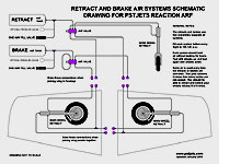
Air System Schematic Drawing for PST retracts and brakes. This is your "roadmap" to understanding how all of the components and air lines are hooked up. You should really print this drawing (use one of the links below) so it's handy when all those air lines start looking like a bowl of spaghetti.

PDF: Air System Schematic Drawing - PST Package
PDF: Air System Schematic Drawing - Pro-Links Deluxe
Click to Enlarge 
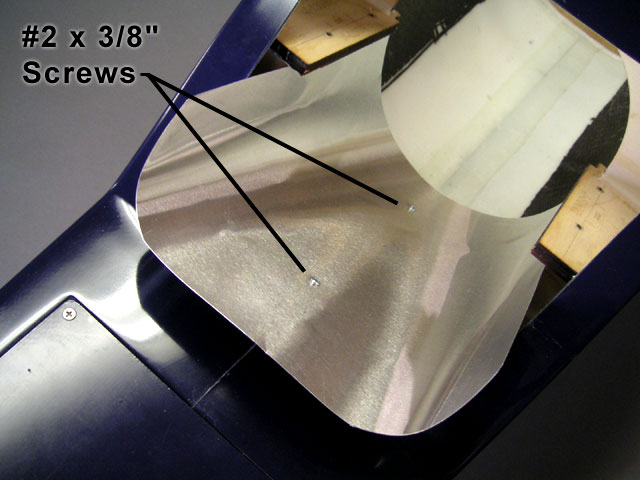
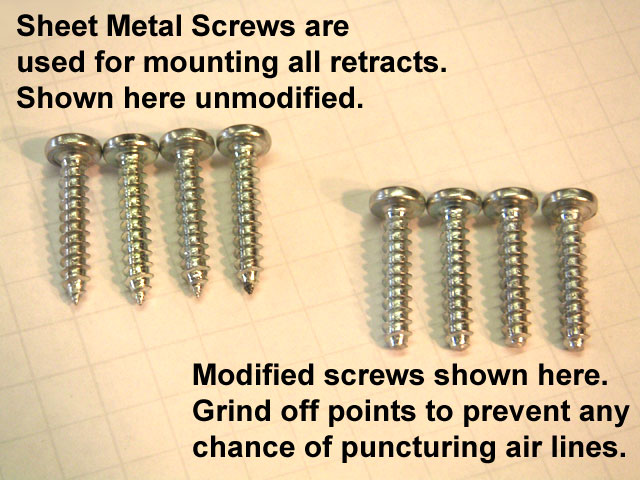
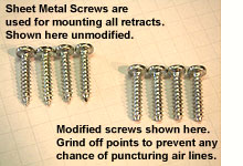
Prepare Your Mounting Screws. Sheet metal screws are provided for mounting all three retracts because they are easier to install than bolts and blind nuts, and they might protect the airframe by ripping out cleanly in a rough landing (something I don't care to test!). However, the sharp points could possibly damage air lines, so use a grinder to round them off slightly.
Click to Enlarge 
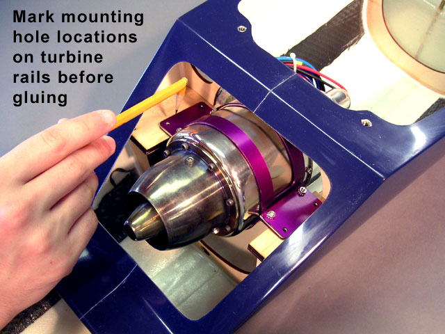
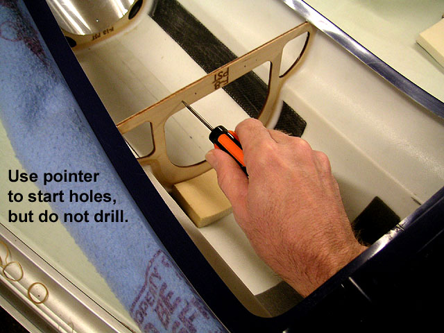
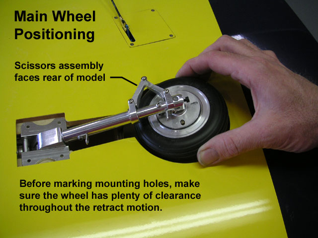
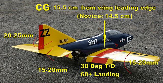
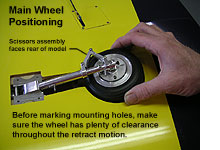
Mark the Main Wheel Retract Mounting Holes. This is a little trickier to do than it may appear at first. If you just lay the assembly in place with the wheel centered in the wheel well, it may not be in the ideal position. You need to move the wheel and strut up and down and watch for clearance around the wheel as it passes through the cutout in the wing skin. When satisfied with the position, mark the mounting holes, remove the retract, and drill at the marks with a 3/32" drill bit.
Click to Enlarge 
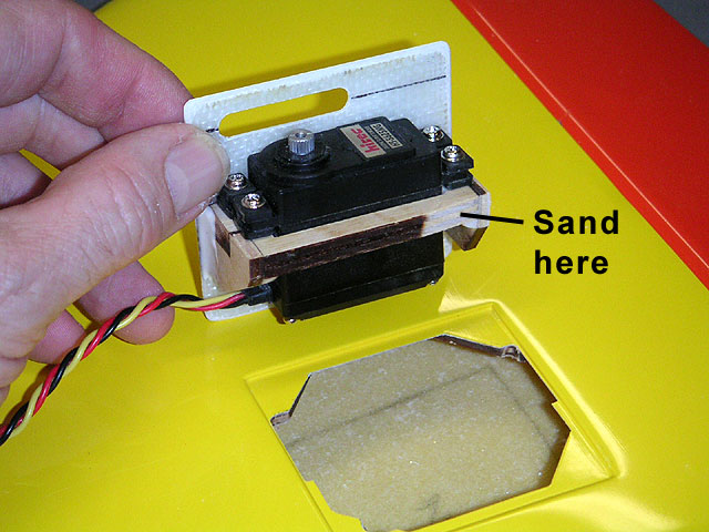
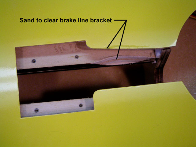
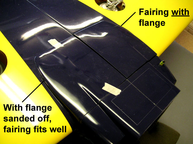
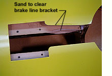
Prepare the Mounting Area. The upper "L" bracket for the brake air line interferes with the wing skin and plywood rail, so I used a Dremel tool with a sanding drum to provide clearance in this area.
Click to Enlarge 
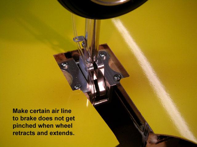
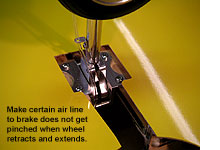
Install the Main Wheel Retracts. Thread the retract air lines through the wing, then attach them to fittings on the side and end of the retract cylinder. Now you can slide the retract unit in place and bolt it down with four mounting screws. Add the brake air line, then work the retract up and down a few times by hand to make sure it stays clear at all times.
Click to Enlarge 
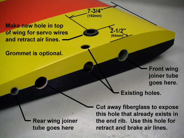
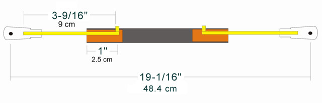
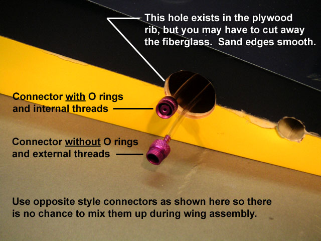
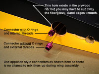
Finish the Air Lines in the Wing. Refer to the Retract and Brake Schematic Diagram and finish adding the "T" fittings and end connectors as shown. Each wing panel will have two air lines coming out of the wing root, and two air lines coming 
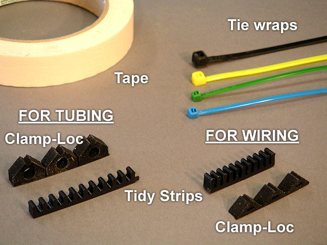
out of the upper skin through the same holes as the servo wires. I added yellow tape strips to my brake lines at the ends to help identify them.
Click to Enlarge 
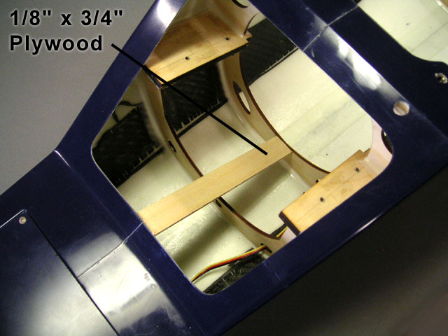
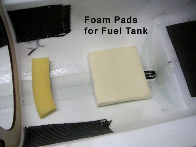
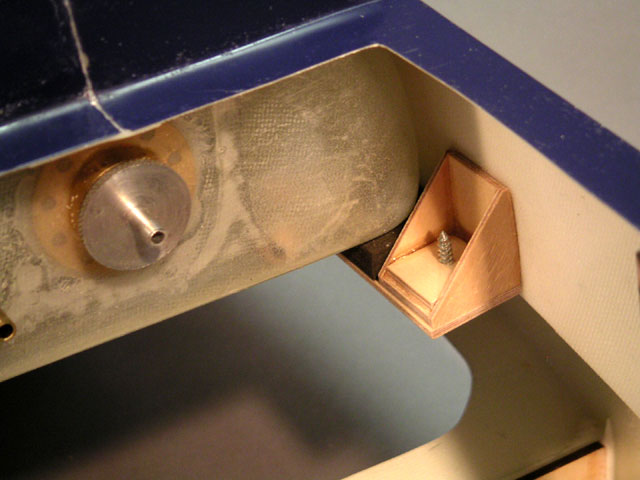
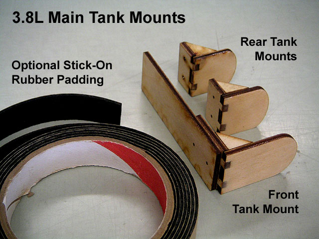
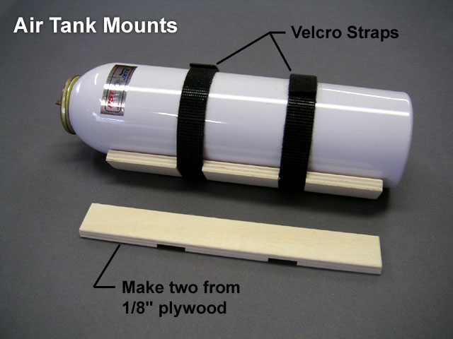
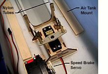
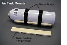
Prepare Two Air Tank Mounts. Now we move to the front fuselage section to install the nose wheel retract, the nosewheel steering servo, and the air tanks. Materials for the air tank mounts are not 
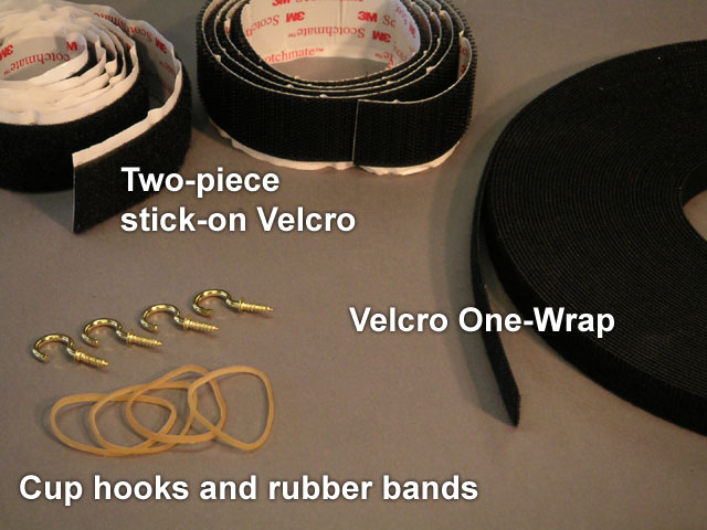
provided, so the method shown here is just a suggestion. I used two layers of 1/8" lite-ply, with gaps in the bottom layer for the 1/2" velcro straps.
Click to Enlarge 
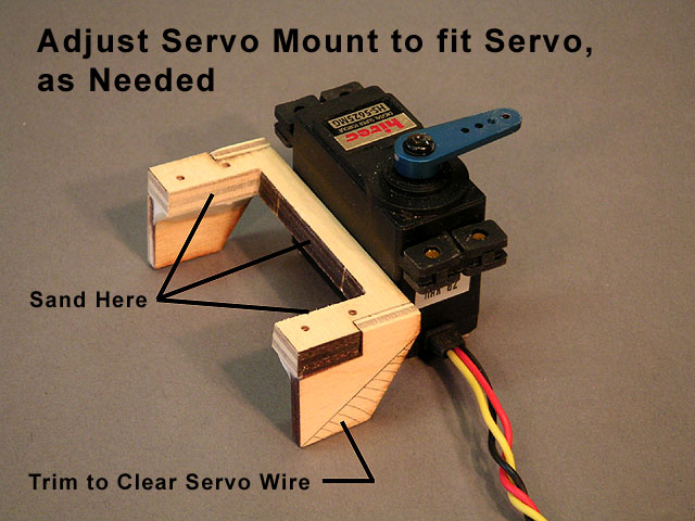
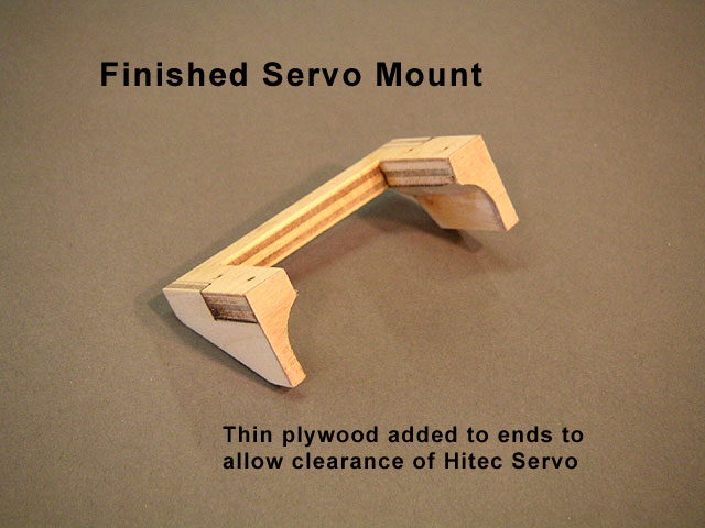
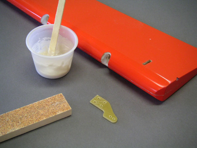
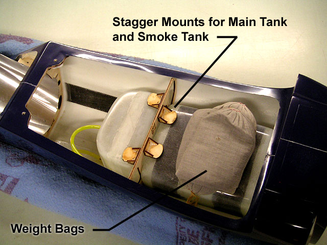
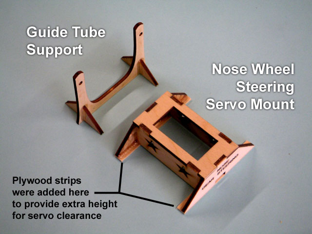
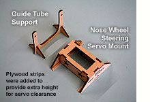
Build the Guide Tube Support and Steering Servo Mount. These plywood parts are provided with the ARF, but they need to be assembled and glued together using CA or epoxy. My servo was a little tall, so I added plywood strips on the bottom to raise the mount slightly. I also added small plywood pads underneath the screw holes at each end to provide extra thickness. Use epoxy to glue the servo mount, guide tube support, and tank mounts to the bottom of the fuselage.
Click to Enlarge 
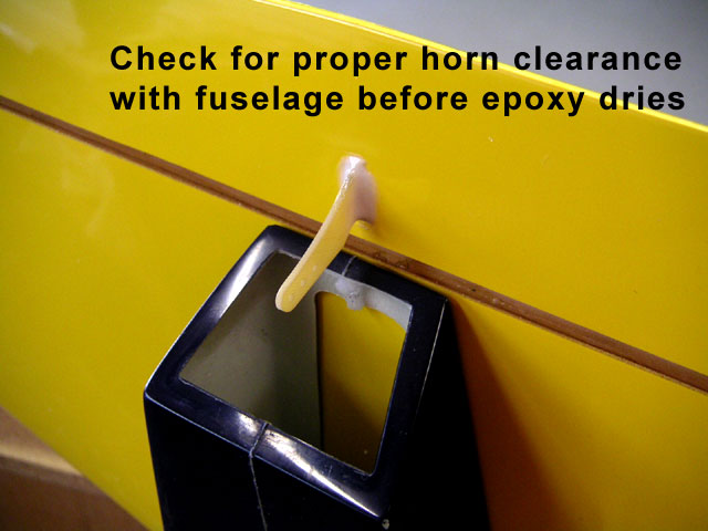
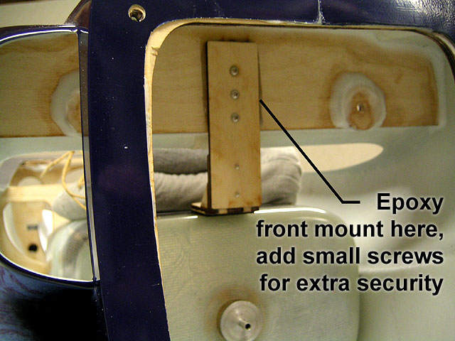
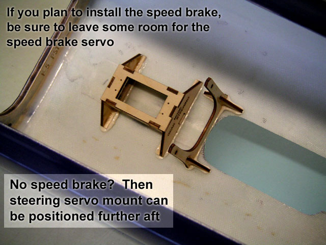
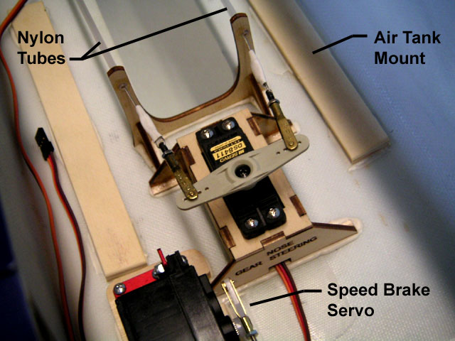
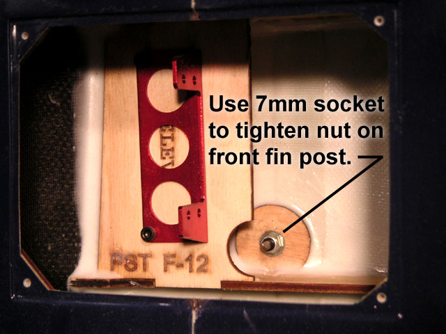
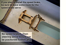
Glue Mount and Support in Place. The servo mount can be mounted further aft than shown here, but this one was positioned as far forward as possible to leave room for a speedbrake servo (to be installed later).

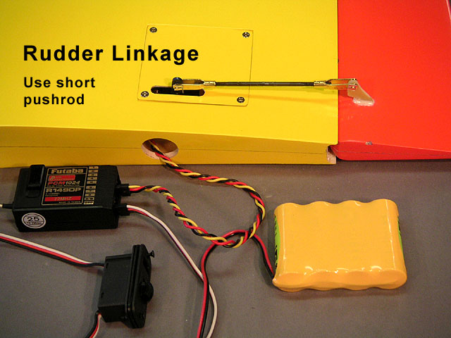
Add Nose Wheel Strut. As with the mains, work the nose strut up and down a few times to make sure it is positioned properly before marking the mounting holes. Attach air lines to the nose wheel retract unit, then bolt it in place.
Click to Enlarge 
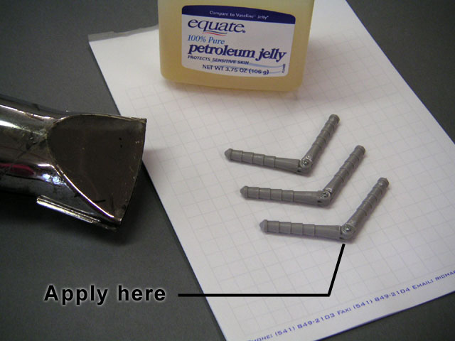
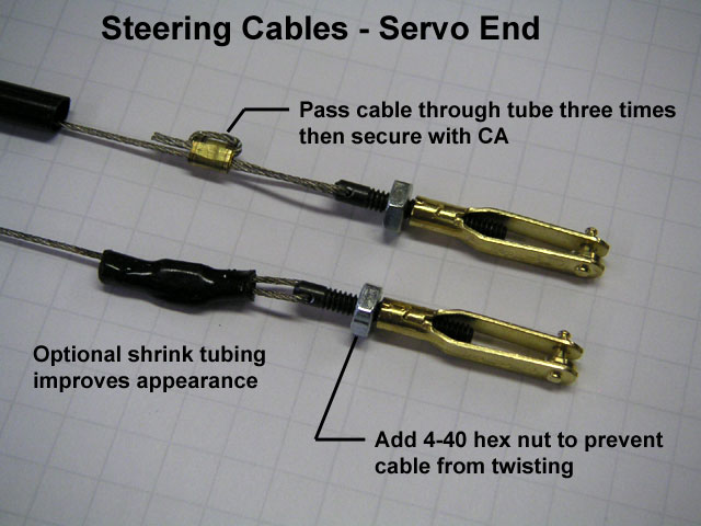
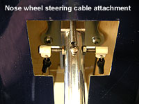
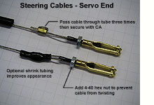
Assemble the Steering Cables, Servo End. The nose wheel uses pull-pull cables for steering. The cables need to be guided around the wheel and strut when retracted using nylon guide tubes. For some odd reason, the tubes are not included with the ARF - use inner nyrod tubing or something similar. The cable and most of the hardware shown here is included with the ARF (except for the 4-40 hex nuts and shrink tubing).
Click to Enlarge 
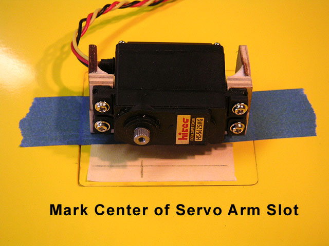
Install Steering Servo. Use a double servo arm as shown. Connect the cables to the arm, using holes that have the same spacing as the two nylon attach points on the nose wheel strut.

NOTE: Use a separate radio channel for nose wheel steering slaved to the rudder channel (do not use a Y-connector) so that you can program the steering alone. Generally, you only need a small amount of movement in the nose wheel, maybe 15 degrees each direction for good ground handling.
Click to Enlarge 
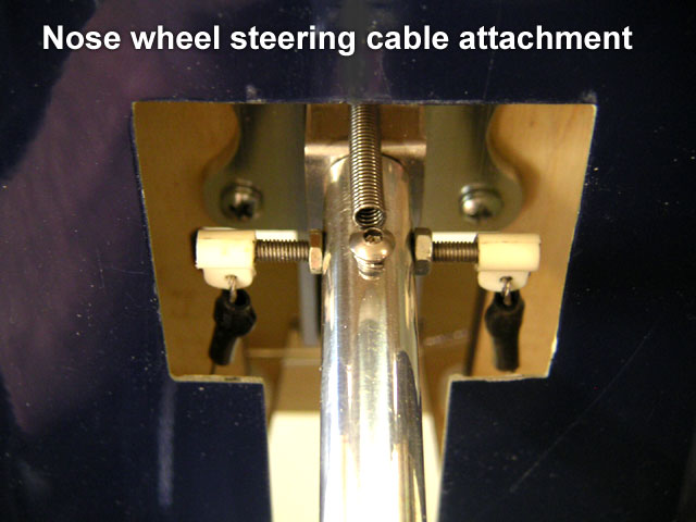
Finish the Steering Cables. For this step, be sure to have the servo plugged into the receiver and the radio switched on so it stays centered. Working with one cable at a time, finish the ends at the nose wheel strut as shown in the photo. The idea here is to make them as close to proper length as possible, then adjust them at the servo end if needed. There should be no slack in the cables, but they do not need to be banjo tight. If they are too tight, the cables could prevent the nose strut from locking in the down position.
Click to Enlarge 
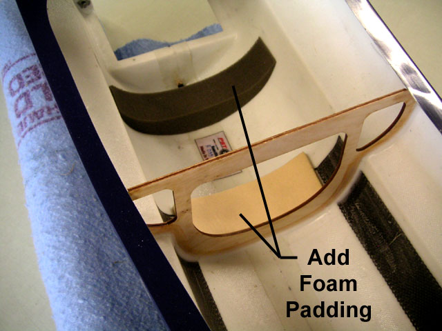
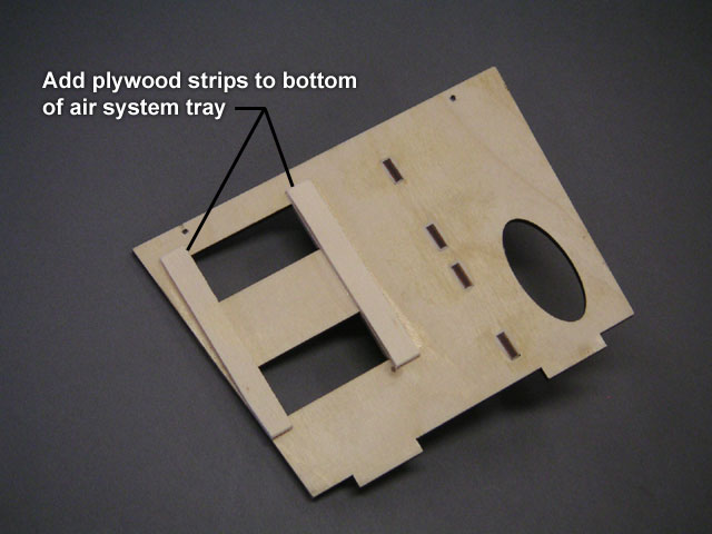
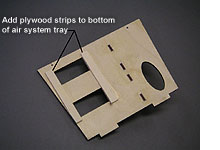
Prepare the Air System Tray. I added plywood strips as shown in the photo to the bottom of the tray. Depending on your servos and how you intend to connect them to the valves, you may want to add strips like this to the top of the tray to raise the servos. Plan ahead.
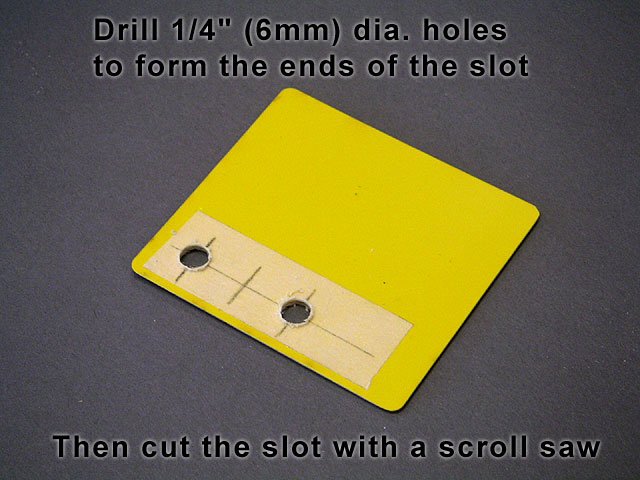
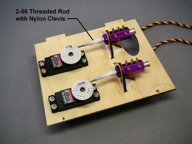
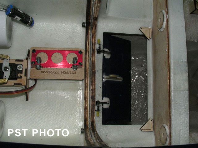
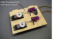
Install the Servos and Air Valves. These linkages are not provided with the ARF package. I decided to use 2-56 threaded rods with nylon clevises, connected to the servo arms with low-tech, but trustworthy "Z" bends. As you can see, the air valves only move about 1/4" (6 mm), so use short servo arms and program the endpoints carefully so the servos do not stall. At this point, either valve can be used for retracts and the other for brakes.
Click to Enlarge 
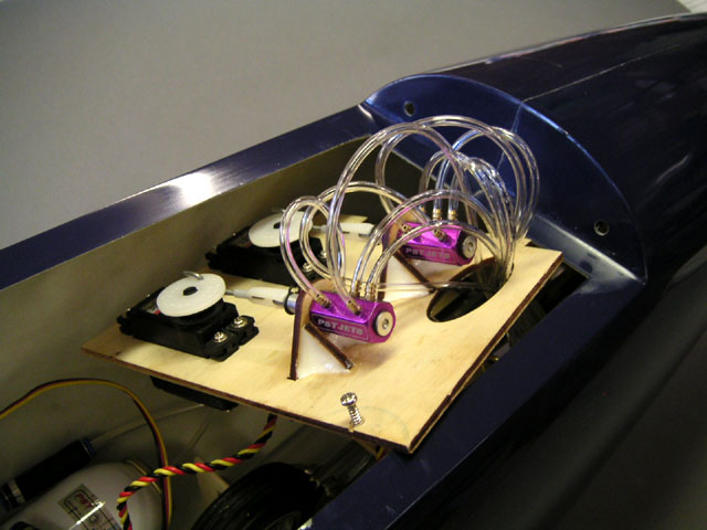
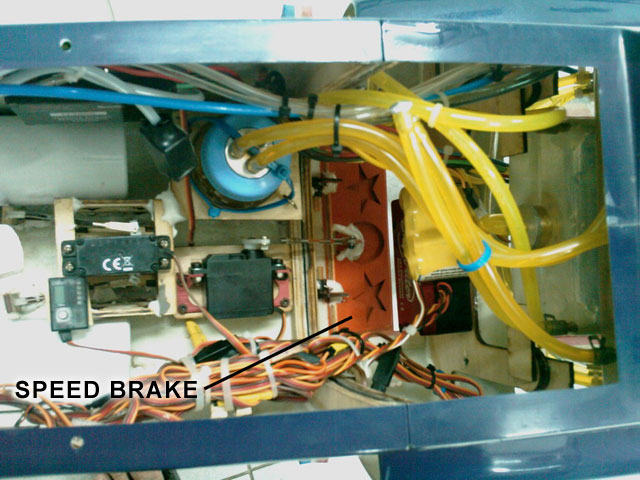
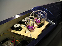
Attach the Air Lines to the Valves. As you can see, there is quite a jumble of air lines at the valves. They will all tuck neatly under the nose, so your main concern is to avoid kinks. Route all of the air lines down through the oval cutout in the tray and the holes in the bulkhead. Leave enough slack in the air lines so you can pull out the plywood tray as shown in the photo.
Click to Enlarge 
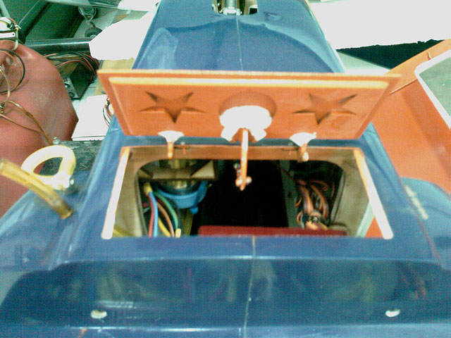
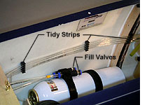
Route the Air Lines and Fill Valves. I used tidy strips inside the fuselage to keep the air lines from flopping around. Be sure to leave your air lines plenty long so it is easy to hook them up to the air lines coming out of the wing.

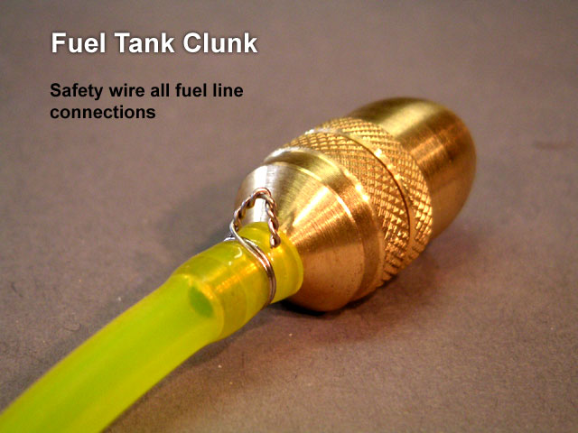
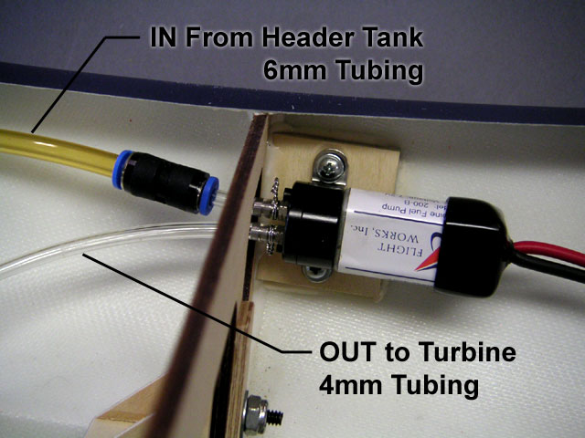
The fill valves provided with the retract system are Festo one-way valves. These work fine, but they do not fit the air lines. The solution is to use 4mm tubing (typical turbine fuel tubing) for the fill valves. Where the larger tubing meets the "T" fitting, use a short piece of air line on the barb, then force the 4mm tubing over the smaller tubing. When not in use, my fill valves are secured to the air tanks using another strip of velcro. Notice the brake fill valve is marked with yellow tape.


WING FAIRINGS

I believe the wing fairings were intended to be glued to the wing with the outer flanges intact, as provided by the factory. However, like most small fiberglass parts, mine showed a tendency to warp and just did not fit very well. At that point, I decided to cut off the flanges (using a Dremel tool and drum sander), and the fit was much improved. Yes, you lose some gluing surface this way, but the fairings are not structural parts - they are just there to look good.

Click to Enlarge Click to Enlarge Click to Enlarge


GENERAL INSTRUCTIONS
- Once the fairings are sanded to fit, tape them in place on the wing and fuselage. Add masking tape all around the outer edges, then remove the fairings.
- Roughen the surface of the wing with 80-grit sandpaper at all points where the fairing makes contact.
- Remove the masking tape, then tape the fairings back into their final position.
- I used a few drops of thin CA to tack glue the fairings. CAUTION! Thin CA tends to go everywhere, so apply it carefully and sparingly. You do not want to glue the wing halves together, or the wing to the fuselage!
- Remove the wing and finish gluing all around the fairings with thin or medium CA.
- Mine ended up with a pretty big gap at the root, but the fairing is securely glued everywhere else so I am not going to worry about it (this area is not visible when the model is assembled).


FUSELAGE ASSEMBLY

Click to Enlarge The question about bolting the front fuselage to the rear fuselage is not HOW?, but WHEN? The "how" is easy - simply use the four supplied socket-head bolts with some lock-tite to join the sections. The fiberglass flanges do not need to be glued, but you can add epoxy to the joint if you wish. I like the idea of possibly taking it apart some time in the future so I just used the bolts.

The "when" is a little trickier. It is tempting to bolt it together early to see how it looks, and leave it that way while working on it. However, I found it very easy to work on the separate sections for as long as practical. The flat bulkheads make it possible to stand the sections vertically, which was handy at times. I finally bolted the sections together when it was time to run the retract and brake air lines from the valves back to the wing opening. At that point, the fuel system was completely installed in the rear fuselage section, the turbine was installed, and the nose wheel steering system was installed in the front fuselage section.


CANOPY/HATCH ASSEMBLY

The canopy also serves as the main hatch for the forward fuselage. It is assembled from three main pieces: the fiberglass frame, the clear canopy, and the black plastic cockpit tub. A printed instrument panel is included to stick on the cockpit tub. You may add your own pilot figure if you wish. The cockpit is a focal point with any airplane, so a little extra effort here can really personalize your Reaction.

Click to Enlarge Click to Enlarge Click to Enlarge


GENERAL INSTRUCTIONS
- The canopy glues to the inside of the frame. Trim the canopy about 1/4" oversize, smooth any bumps on the inside of the frame, then tape the canopy in place all around on the outside surface. You want these parts to make good contact with no gaps.
- Position the assembly upside down with a block of wood under each end of the frame. Add a weight bag inside the canopy to help keep it in contact with the frame.
- Use a white canopy glue like Zap Formula 560. Force glue under the edge of the canopy, all the way around. I heated and bent a long CA nozzle for this step. You may have to lift the edge of the canopy with a fingernail as you go.
- Canopy glue will eventually dry clear, but mine took several days. Once dry, remove the tape and simply rub away any dried glue that may have oozed to the outside.
- The printed instrument panel that comes with the ARF is easy to stick in place. However, mine started to wrinkle and lift after about a year. I suggest you add a layer of clear plastic over the panel, held with a few small screws.
- If you use a pilot figure, be sure to glue him securely! Not only at the base, but anything that might come loose during flight like sunglasses, helmets, masks, etc...
- The cockpit tub also glues to the inside of the frame. Trim the edges just enough so it will wiggle into place, leaving at least 1/8" (3mm) of overlap on each side. Add a notch to each side to clear the globs of glue that are holding the frame pins in place. I also suggest cutting a finger hole in the bottom of the tub, under the instrument panel, which will help you later during the gluing process.
- Before you glue the tub in place, this is your last chance to clean the inside surface of the canopy. Also vacuum or wipe any dust on the tub that could come loose later.
- Use fast-drying epoxy to glue the tub in place, and hold it until dry. As shown in the last photo, leave a dry section (no glue) on each side in the area of the pins. This will allow a small amount of flexibility which may be needed to get the pins to engage properly.
- It may go without saying, but always take the time to be sure your canopy latches firmly before you fly. I've seen a lot of jet canopies fly off because the pilot rushed to get in the air after starting the turbine.

Click here for detailed pilot mounting instructions.


VARIOUS EQUIPMENT INSTALLATIONS - FINAL TOUCHES

At this point, your turbine, fuel tanks, and retracts are installed. Those items are relatively easy, because there isn't much choice about where they go. But when it comes to installing things like receivers, ECUs, and fuel pumps, there are many more possibilities. This is where the instructions become more like guidelines. The best advice I have is: Plan Ahead!

Click to Enlarge Fuel Pump Installation. In general, the fuel pump can be one of the "noisiest" components in the model in terms of RF emissions. It is best to keep your pump far away from your receiver, ECU, and any other wiring as practical. My fuel pump is mounted to a metal bracket which is screwed to a plywood pad. Other pumps may need to be held in place with tie wraps. I prefer to use 6mm tubing from the header tank to the fuel pump because I think it is easier on the pump to draw through the larger tubing. A Festo 6mm-4mm reducer is used just before the pump inlet.
Click to Enlarge Turbine Connections. If you are new to turbines, the variety of wires and tubes that need connecting and routing can seem overwhelming. Take them one at a time, and your understanding and confidence will grow. Here you can see the main fuel line with a fuel filter just before the turbine. Down low is the EGT connector stuck in place with Velcro. I like Velcro for this purpose because it provides a bit of cushioning. Notice the support block with two screws and rubber bands to hold the bundle of turbine wires.
Click to Enlarge Gas Solenoid. Again, two-piece Velcro is used to hold the gas solenoid in place on the side of the fuselage. My installation does not have an onboard propane canister - I prefer to use an external canister for starting. PST does not use a solenoid for the fuel (kerosene), although one can be installed if you wish (the ECU is set up for the option). Notice the numerous tie wraps used to hold the wire bundle together.
Click to Enlarge ECU and Receiver Shelves. This is where you really need to plan ahead. I like to keep my ECU and receiver separated as far as possible. I also want my antenna a good distance from the ECU and other wiring. In the end, I added these plywood shelves as shown (not included with ARF package). The receiver goes well forward and its antenna (72 mHZ) will be routed along the right-hand side of the model with the air lines. The ECU is mounted well aft and all of its wiring will run along the left-hand side of the model. There is still plenty of room for access to the air tanks and steering servo.
Click to Enlarge Receiver Installation. As a long-time modeler, I still like to wrap my receiver in foam even though there is minimal vibration in a jet. At least it will be protected a little bit in case of a crash. It is held to the receiver shelf with cup hooks and rubber bands. The antenna is simply taped to the fuselage side. Further aft, I was careful to keep the antenna away from the carbon fiber reinforcing strips molded into the fuselage.
Click to Enlarge ECU and Related Equipment. For some reason, I can live without the ECU being wrapped in foam. However, there is a foam pad underneath for a bit of cushioning. Notice how all of the connections and switches and fuel valve are all easy to access. I will need to get at all of them before and after every flight, so it makes life easier if they are all conveniently handy. NOTE: It is a good habit to unplug the ECU battery between flights, even if the switch is off.
Click to Enlarge Reaction X Battery Installation. The battery rack in the nose is designed to use tie wraps. These lithium batteries are cushioned with rubber strips. A smaller battery for the smoke system was added later, under the receiver battery.


MOUNTING THE TAIL SURFACES

You can avoid a lot of hangar rash by leaving the tail surfaces off the model until the end of assembly. While installing the tanks, turbine, ECU and radio system, you are constantly flipping the fuselage from right-side-up to upside-down, so it's nice to not have to worry about banging the tail. I recommend using balldrivers (instead of allen wrenches) to avoid over-tightening.

Click to Enlarge Click to Enlarge Click to Enlarge


NOTE: These instructions are for the removable tail surfaces, which are now a standard feature. Early ARFs had non-removable tail surfaces that need to be epoxied in place.

Click here for detailed instructions for mounting the earlier glue-on tail surfaces.


OPTIONAL SPEED BRAKE

The outline for the optional speed brake is molded into the bottom of the fuselage, between the inlets. Beyond that, it is up to the builder to reinforce the cutout, install hinges, and the activating mechanism. After flight testing, the PST crew decided the speed brake is not necessary, but the option is still there for any builders who might like to give it a go.

UPDATE FROM PST: I have more hours with the Reaction now and I still think that the speed brake is a nice feature to have but not required... The good thing with speed brake is that it allows more precision landing but requires good energy management!!

Click to Enlarge Speed Brake Installation Shown here is the speed brake with hinges and horn, and the servo mount. The servo mount is included with the ARF, but nothing else is provided. I'm not sure what PST used for a horn and hinges, but just about any type of control horn can be used. Offset hinges are available from Dreamworks. Several brands should work well, including Robart, BVM, and Tamjets. Notice the plywood triangles at the rear corners of the opening to keep the speed brake flush with the fuselage when retracted. You can program the speed brake to deploy with a separate channel or mix it with the flaps to deploy automatically.

Click to Enlarge Click to Enlarge


BALANCE RANGE AND CONTROL THROWS


Balance Range: You must balance your model between 5-3/4" and 6-1/8" (14.5 cm to 15.5 cm) aft of the wing leading edge where it meets the fuselage side. Do not exceed the rear limit! Balance with main fuel tank empty, and wheels retracted. Unless you use a lot of heavy batteries in the nose, it is likely that you will need to add quite a bit of lead to make the model balance properly. Every modeler hates to add dead weight, but grit your teeth and add enough to be in the forward half of the balance range for the first flight. You can put lead shot in small plastic bags and remove some later as desired. Be sure to also check the lateral balance and add weight to one of the wingtips if necessary to balance.

Control Throws: The chart below gives the recommended control throws. I suggest that you use the low rate throws for the first flight. You can experiment with the high rates once you get comfortable with the flight characteristics. Many jet pilots also like to use exponential for a softer feel at high speed. PST recommends 15% exponential on ailerons, 25% on elevator. As with any model, you need to fine tune the programming to suit your taste as a pilot.

HIGH RATE LOW RATE
ELEVATOR - Each Direction 13/16" (20mm) 5/8" (15mm)
AILERONS - Each Direction 13/16" (20mm) 5/8" (15mm)
RUDDER - Each Direction 1" (25mm) 13/16" (20mm)
FLAPS - Takeoff/Landing 30 Degrees / 60 Degrees

IMPORTANT! You will also need to mix in a small amount of down elevator with flaps:
Takeoff Flaps - 1mm Down / Landing Flaps - 1.5mm Down


<Back to previous page


home | venture 60 | flyin' king | delta vortex | super flyin' king | reaction 54 | about bte | prices | ordering | in the works


pilots | cable cutters | fourmost | handibond | builder galleries | plans page | double whammy | uav projects | vintage rc

© 2016 Bruce Tharpe Engineering  |  e-mail BTE: bruce@btemodels.com